4.6 Hierarchical control | JAVA 3D Programming | Chapter 4
Many 3D applications define a complex
scenegraph hierarchy. An important function of the scenegraph is to enforce the
geometric and spatial relationships that the scenegraph defines. Just as when
the F1 car was moved its constituent parts were also moved. This principle is
central to applications that require hierarchical control.
To illustrate these principles, in this section I’ll show you a Java 3D scenegraph to animate a model of a human arm (figure 4.13). Requirements of the model are:
•
Shoulder joint can be rotated
• Elbow joint can be rotated
• Wrist joint can be rotated
• Upper finger joints can be rotated
This model is obviously hierarchical.
It would be most usual if when the elbow joint was rotated the lower arm and
the fingers were not also displaced. An important principle of the scenegraph
is that the position of a child Node only depends upon the positions of its
parent Nodes. In other words, the position of the end of the little finger
depends upon
•
Length of little finger (defines the offset from the center of rotation)
• Rotation of little finger joint
• Length of wrist
• Rotation of the wrist joint
• Length of lower arm
• Rotation of the elbow joint
• Length of upper arm
• Rotation of the should joint
Converting the rotational requirements
into a scenegraph hierarchical model produces a structure such as that in
figure 4.14. Note that we have switched to a left−to−right tree representation
of the scenegraph hierarchy to save space.
As with most things in life, things
are not quite that simple. There are a few implementation−related issues that
must also be resolved through the scenegraph structure. The scenegraph in
figure 4.14 would be fine if you required just a static model of the human arm,
but it would be nice to be able to illustrate the example by rotating the
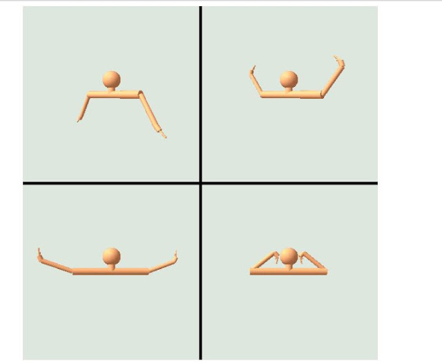
various joints to animate the model (as shown in figure 4.15). To simplify
rotating the joints you must introduce another TransformGroup into the
hierarchy for each limb to store the current joint rotation value. Two
TransformGroups are thus required, one to store the length of the limb (i.e.,
the offset of the coordinate system of the next limb relative to the current
limb’s coordinate system) and one to store the joint rotation.
Unfortunately another minor
implementation issue arises. The Cylinder geometric primitive that you are
using to create the limbs in the model is created with 0,0,0 at the center of
the cylinder. In other words, if you create a cylinder of length L, it will
stretch from –L/2 to L/2 in the y direction, with a given radius. We would like
our cylinders to stretch from 0 to L in the y direction, so an additional
TransformGroup is required to shift the cylinder upward by L/2 in the y
direction.
When these refinements have been made,
the scenegraph for the arm looks a little more complicated than our initial
design but it still fulfills our rotation requirements for each joint. The
completed scenegraph is illustrated in figure 4.16.
To verify the rotational requirements,
you can walk up the scenegraph hierarchy from the end of Finger 1. Walking up
the hierarchy will tell you what the position of the end of Finger 1 relies
upon:
• Finger 1: TG Offset (the length of
finger 1)
• Finger 1: TG
Joint (the rotation of finger 1)
• Wrist: TG
Offset (the length of the wrist)
• Wrist: TG
Joint (the rotation of the wrist)
• Lower Arm:
TG Offset (the length of the lower arm)
• Lower Arm:
TG Joint (the rotation of the lower arm)
• Upper Arm:
TG Offset (the length of the upper arm)
• Upper Arm:
TG Joint (the rotation of the upper arm)
• Shoulder: TG
Shoulder (position/rotation of the shoulder)
The rotational requirements have been
satisfied, the scenegraph models the hierarchical structure of the human arm.
There are two slightly undesirable
implications of the scenegraph as we have designed it. First, the length of the
cylinder that we used for the geometry of the arm is unrelated to the length of
the limb, inasmuch as the length of the Cylinder effects the next limb in the
hierarchy. In this application, TG Offset and the length of the cylinder we
created just happen to correspond. Second, the wrist and fingers are poorly
modeled, as the fingers should be offset relative to one another. As modeled
here the fingers all attach to the same location on the wrist.


Comments
Post a Comment